I know it's been a long time since I last blogged but I've made up for it by making this one ridiculously long haha. I'm excited to talk about High Dynamic Range Imaging (HDRI) and its implementation in the I-Novae Engine. HDRI is one of those features that I get really excited about because it's shiny and I like shiny things. In fact most other people seem to like shiny things as well, which has led me to develop my Universal Law of the Shiny which states "If you build it, and it's shiny, they will come".
Hold onto your Butts
This blog article has been written for people who aren't graphics programmers or physicists however, that being said, for you to understand how the I-Novae Engine implements HDR you must first understand some radiometry, photometry, and color theory. I'll do my best to explain it all at a high level but some of this may be a bit intense. My hope is that you at least find it interesting.
What's High Dynamic Range Anyway?
In the real world there is this stuff that gets all over the place called light. Light is a truly fascinating substance as it affects everything we do and even how we all got here in the first place. While there are entire libraries filled with literature about light all we need to focus on for the purpose of this blog article is that the human eye has evolved to catch incoming light and turn it into the picture you are currently viewing. Unfortunately there is a problem with this process. The range of luminance that the eye encounters is so great, approximately 1,000,000,000:1 from night to a sunny afternoon, that the eye cannot make sense of all of that light (or lack thereof).
In response to this problem the human eye establishes a specific range of luminances that will be turned into visible colors. All luminances below the bottom of this range will show up as black and all luminances above this range will show up as white. These thresholds are also known as the black point and the white point. The eye has another extremely helpful feature for dealing with all of this light: it can shift the range of visible luminances based on the average luminance of its environment. This is referred to as having a dynamic range and explains why walking outside after being indoors will result in being blinded by light with an intensity outside of your current visible range. As the eye adapts to its new surroundings everything in the environment shifts from white or black into its appropriate visible color.
The Cake is a Lie
At some point in your life you or somebody you know has probably bought a big, shiny new HDTV. The first time you turned it on it's likely you were amazed by the crisp picture and bright colors. Unfortunately, as is often the way of things in life, the cake is a lie. Modern HDTV's only have a brightness of ~250 cd/m2 and a contrast ratio around 1,000:1 to 10,000:1! In comparison a cloudy afternoon has a luminous intensity of 35,000 cd/m2 and as I mentioned before our eyes have a contrast ratio of 1,000,000,000:1. For this reason HDTV's and other displays like it are referred to as Low Dynamic Range (LDR) displays. HDRI is the process of mapping the high dynamic range of luminances you encounter in the real world onto the low dynamic range of a modern display device.
Electromagnetic Radiation
 |
| Visible Light Spectrum |
The Colors Duke, the Colors!
Now we know what HDR is and what light is but how do our eyes turn all of that into color? The human eye is composed of two different categories of cells, known as rods and cones, that turn light into color. Rods are used primarily during low-light conditions, also known as scotopic lighting conditions, and are most sensitive to the short (blue) wavelengths of light which is why everything at night has a bluish tint. Rods are more sensitive than cones to changes in luminance however they are not good at rapidly changing their dynamic range which is why it takes a long time for you to achieve 100% night vision.
Cones, used during bright, photopic lighting conditions, are everything rods aren't. They are most sensitive to local contrast instead of luminance however they are capable of rapidly shifting their current dynamic range. Cones come in three varieties known as Long, Medium, and Short (LMS) cone cells. LMS refers to the length of the waves of light that a cone cell has highest sensitivity for. These wavelengths line up very conveniently with the primary wavelengths for Red, Green, and Blue (RGB) light respectively. RGB provides the basis for all digital color generation but before I can get into that I have one other thing I need to cover.
Perception of Color
As I mentioned in the last paragraph cone cells, which are used under the vast majority of lighting conditions we encounter on a day-to-day basis, come in three flavors each of which is sensitive to a specific range of wavelengths of light. Way back in 1931 a bunch of scientists from the International Commission on Illumination (CIE) got together to wave their hands in the air while whispering dark incantations. A byproduct of this hand waving was some science that determined just how sensitive each of the LMS cone cells are to the various wavelengths of light. They also discovered that if you apply a sensitivity curve for each type of cone cell to a spectrum of light and mix in a dash of voodoo black magic you end up with three values which together are referred to as the CIE 1931 XYZ Color Space. The process of figuring out how the human eye perceives light, from which the XYZ color space is derived, is referred to as photometry.
Are we there yet? Almost...
Ok so now we have XYZ and RGB and what the heck is the difference? To answer that you first need to know how a display device such as a TV outputs color. Everybody has heard about this thing called resolution. It's what makes an HDTV an HDTV. For example 1080p, currently the holy grail of HDTV, means that the screen has 1080 horizontal rows of pixels and (usually) 1920 vertical columns of pixels. Each of these pixels is capable of emitting red, green, and blue light in a range commonly between 0 and 250 cd/m2.
Every display, like any other light source, has its own spectral power distribution (SPD). An SPD represents a distribution of spectral power per watt of radiant flux. For example HDTV's have an SPD referred to as D65 which is equivalent to the SPD of midday sunlight in western Europe. Thus XYZ is a device independent color space and for display it must be transformed into a device dependent RGB color space using weights derived from the SPD of the output device - a process that ensures the appropriate quantities of red, green, and blue light are emitted to achieve the desired color.
Gamut and Gamma
 |
| Gamut of the sRGB color space relative to the human eye |
With 24-bit color each R, G, and B channel for a pixel is represented by 8-bits which can hold a number between 0 and 255 (inclusive). An increase of 1 in any of the channels means an increase in the intensity of light emitted for that channel by a factor of 0.3%. The problem with this is that the human eye does not perceive an increase in intensity linearly. Most display devices operate in the sRGB color space which mimics the logarithmic increase in perceived intensity by the human eye. This logarithmic curve is referred to as the gamma curve. Since all lighting for CG/games is done in a linear color space, same as in real life, which means that 1 W/m2 of incident irradiance plus 1 W/m2 of incident irradiance equals 2 W/m2 of incident irradiance, the result must be gamma corrected before it's displayed on screen. If an image is not gamma corrected it will look darker than it should which creates all sorts of problems.
Lighting and Color in the I-Novae Engine
I know that was a lot of theory, I'm sorry, but it's important for understanding how and why the I-Novae Engine handles light/color. In most game engines when you place a light in a scene you assign it an RGB color. This color is in fact usually an uncorrected sRGB color which, for the aforementioned reasons, is oh so very wrong. When you place a light in a scene with the I-Novae Engine you specify its color in the form of spectral intensity for the red, green, and blue wavelengths. In practice, on current generation hardware, this will look similar to specifying color in linear RGB however there is an important distinction.
In the real world the way surfaces reflect, transmit, and absorb light is wavelength dependent. For example the sky is blue because the atmosphere primarily scatters the shorter (blue) wavelengths of light. By using radiometric quantities the I-Novae Engine is future proofing itself so that it is capable of handling more advanced and realistic materials as GPU's continue to become more powerful. It's also well suited to a variety of global illumination solutions - one of the major new trends in next-gen graphics.
Textures
If you're a texture artist working with the I-Novae Engine I am happy to say that most of the textures you've created should work as is without any problems. However there is a possibility they may look similar but different. This is because the I-Novae Editor automatically assumes every texture you import needs to be gamma corrected. You can tell the editor to skip this step for linear data such as normal maps but for anything you traditionally think of as a color you will want to have it corrected. That by itself may make your texture look different in-engine however there's one other problem.
Textures in the I-Novae Engine need to be thought of as the quantity of incident irradiance (incoming light) that is reflected from the RGB wavelengths. For example if you create a texture for a white box that has a red vertical stripe running down the middle the white texels (a texel is a pixel from a texture) means 100% of incident irradiance will be reflected whereas the red stripe means that only 100% of incident irradiance in the red wavelength will be reflected. This is an important distinction from saying "this is a white box with a red stripe" for the following reasons:
- During HDRI post-processing the radiometric quantities of light for each pixel are transformed into the photometric CIE XYZ color space
- Tonemapping converts the XYZ color into xyY, back to XYZ, and then finally into RGB
- Gamma correction is applied as the RGB values are turned into sRGB for final display
Because of these color space transformations and the application of photometric, RGB, and gamma curves the final color could be slightly different than what it would be in a traditional sRGB only color pipeline - which is what the I-Novae Engine used to be.
Tonemapping
As I mentioned before HDRI is the process of converting a high dynamic range image into the low dynamic range of a display device. Specifically, how HDRI accomplishes this is through tonemapping. A good method for accomplishing this task that works well on modern graphics hardware was developed by a guy named Reinhard in a paper he wrote in 2002 called Photographic Tone Reproduction for Digital Images. The Reinhard tonemapping operator as it's called has been a staple of the game industry ever since. Actually the paper was written by 4 guys so I'm not sure why Reinhard gets all of the credit but hey, I just roll with it.
 |
| Scaled color vs scaled luminance |
Exposure and Bloom
Here is the part where I get to talk about everybody's favorite HDR effect - bloom. Bloom is so popular because it makes things appear shiny and, as I said, everybody likes the shiny. It's quite common for people to assume that bloom is HDR because every graphics engine on earth that supports HDR also supports bloom. In truth bloom is a byproduct of HDR caused by the scattering of overexposed parts of an image within your eyeball. Since your monitor/tv can't cause bloom within your eyeball, due to its crappy low dynamic range, graphics programmers have to emulate it manually. The first part of this process is figuring out what the overexposed parts of an image are. Before I can describe how we do this in the I-Novae Engine I first have to describe how exposure works.
Exposure is the total quantity of light that hits a photographic medium over some period of time measured in lux/s. As I mentioned before the human eye perceives increases in luminance with a logarithmic curve. Since most people aren't mathematicians, but controlling exposure is very important, camera manufacturers devised a system of measurement known as the f-stop. An f-stop is the relative aperture of the optical system which controls the percentage of incoming light that is allowed to reach the photographic medium. The higher the f-stop the smaller the aperture and the smaller the quantity of light that reaches the film. F-stop and exposure do not have a 1:1 correlation as things like optical length and shutter speed affect the final exposure however, for our purposes, the f-stop is a good enough approximation that still makes sense to people familiar with photography.
 |
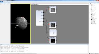
| Unclamped auto-expsoure. That's a whole lot o' shiny! |
When tonemapping an HDR image you have to choose the luminance range of visible colors. This is commonly done by calculating the average scene luminance, deriving the scene middle gray, deriving the scene exposure, and then scaling the per-pixel luminances accordingly. This process is more or less identical to what a digital camera does when calculating its auto-exposure. There is a catch: the human eye and cameras have a limit to their minimum black point and maximum white point whereas auto-exposure algorithms don't. Measured in f-stops the exposure range of the eye is between f/2.1 and f/3.2. Since the I-Novae Engine calculates exposure via f-stops I have implemented, by default, a maximum and minimum exposure range roughly equivalent to that of the human eye. To those of you who are photographers f/3.2 may seem really low. This has to do with the optical length of the eye and refraction caused by eye goo. In practice the I-Novae Engine uses a default minimum aperture size of f/8.3 because our calculations more closely resemble a camera than an eye.
 |
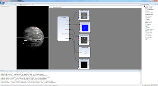
| Clamped auto-exposure and a bright pass of 9 f-stops. |
To determine which parts of an image require bloom you specify the number of f-stops to add to the scene exposure (be it auto-calculated or otherwise) and any remaining color information for the lower exposure is then bloomed. This works great because it follows the same logarithmic curve as the eye and everything looks as it should. I'm still in the process of tweaking the bloom. At the moment it's a bit too... bloomy... but when everything is wrapped up I'll post some new screen shots of stuff more exciting than boxes and orbs.
In Conclusion
Light and color theory are extremely complicated and this blog only scratches the surface of the available literature as well as the details of my own implementation. For those of you who are programmers a great reference implementation was written by Matt Pettineo of Ready At Dawn. My implementation is quite similar to Matt's however mine modulates luminance instead of color and I implement exposure a bit differently as mentioned above. Perhaps after I finish tweaking everything some more I'll provide the technical details in another blog post or something.
It's funny because in high school I hated math and wondered what it could possibly ever be useful for other than basic accounting. Then I got interested in graphics programming and now I use calculus on a regular basis as a part of my job. Moral of the story kids is stay in school and be proactive in your own learning! Oh and buy books, lots of them, because who can remember all of this crap?
Lastly if you see any errors in the information I provide on this blog please don't hesitate to contact me so I can correct it. I hate misinformation and will promptly fix any mistakes. You can reach me via twitter, contact@inovaestudios.com, or the comments section below. Until next time!
